Description:
In this project we build a Fire Alarm System using Arduino and Flame sensor, Here the Flame Sensor is used to detect fire, once fire is detected, a buzzer turns ON and LED glows. Everything is controlled by Arduino Nano (Other Arduinos can be used too).
Circuit Diagram:

Components:
| SR. NO. | COMPONENT | PINOUT DIAGRAM | BUY |
|---|---|---|---|
| 1 | Arduino Nano (Other Arduinos can be used too) | ||
| 2 | LED | ||
| 3 | Buzzer | ||
| 4 | Flame Sensor | ||
| 5 | 220 Ohm Resistor |
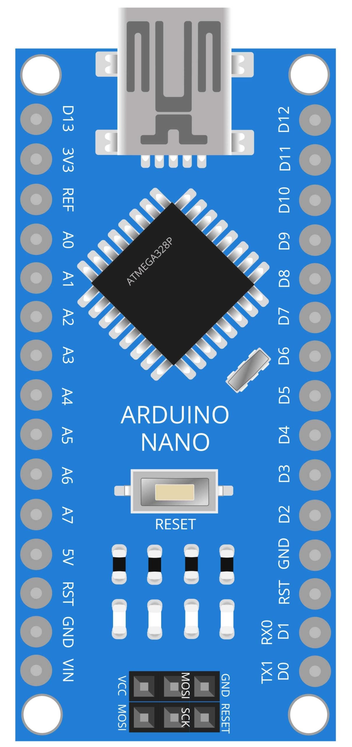
Arduino Nano
The Arduino Nano is a small, breadboard-friendly version of the popular Arduino microcontroller platform. It is based on the ATmega328P microcontroller. It has 14 digital input/output pins, 8 analog inputs, a 16 MHz quartz crystal, a USB connection, and a power jack. The Arduino Nano can be powered via USB or an external power supply, and it can also be programmed using the Arduino IDE.
In this project, the Arduino Nano is used as the brains of the system. The Arduino Nano is connected to a flame sensor, an LED, and a buzzer. The flame sensor detects the presence of fire and sends a signal to the Arduino Nano. The microcontroller is programmed to read the input from the flame sensor and trigger the LED and buzzer in case of fire detection. The LED lights up and the buzzer sounds an alarm to alert the user of a fire hazard. The Arduino Nano is also capable of communicating with other devices or systems, like GSM module to send an SMS or make a call in case of fire detection.
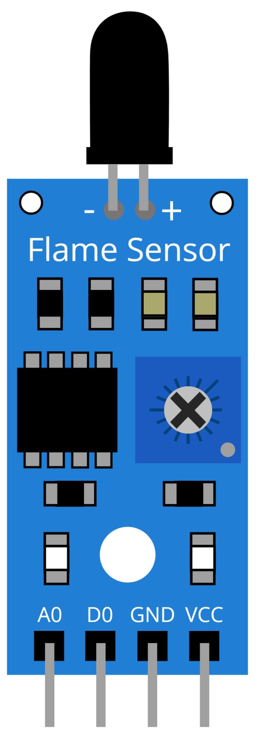
Flame Sensor
A flame sensor is a device that detects the presence of fire by sensing the infrared radiation emitted by a flame. It is often used in fire alarm systems, as well as other applications where fire detection is important. The Flame sensor used in this project is a simple infrared sensor that detects the presence of fire by detecting the infrared radiation emitted by a flame. It has a fast response time and high sensitivity, making it suitable for detecting small flames as well as larger ones.
In this project, the flame sensor is used to detect the presence of fire. The sensor is connected to the Arduino Nano, which is programmed to read the input from the sensor and trigger the LED and buzzer in case of fire detection. The LED lights up and the buzzer sounds an alarm to alert the user of a fire hazard. The flame sensor is highly sensitive to the IR radiation emitted by the flame and it can detect the flame even in low light condition or in smoke. It is a cost-effective and reliable solution for monitoring and alerting in case of fire hazard.
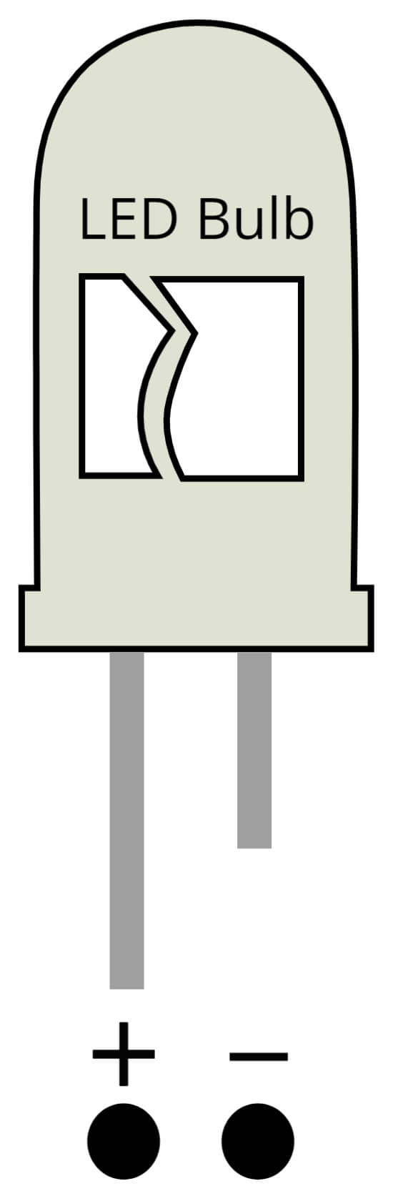
LED
A Light Emitting Diode (LED) is a semiconductor device that emits light when a current is passed through it. LEDs have a wide range of uses, including indicator lights, display screens, and lighting. They are known for their energy efficiency, long life, and fast switching speeds.
In this project, the LED is used as an indicator light to alert the user of a fire hazard. When the flame sensor detects a flame, it sends a signal to the Arduino Nano. The microcontroller is programmed to read the input from the flame sensor and trigger the LED. The LED lights up, providing a visual indication that a fire has been detected. The LED used in this project is a simple red LED, which is a common choice for indicating an alarm or danger.

Buzzer
A buzzer is an electronic device that produces a loud, usually audible sound when an electric current is passed through it. Buzzers are commonly used in alarms, timers, and other devices that need to produce an audible indication.
In this project, the buzzer is used to alert the user of a fire hazard in addition to the LED indicator. When the flame sensor detects a flame, it sends a signal to the Arduino Nano. The microcontroller is programmed to read the input from the flame sensor and trigger the LED and buzzer. The buzzer produces an audible alarm, providing an additional means of alerting the user of a fire hazard.

220 Ohm Resistor
A resistor is a passive component that is used in electronic circuits to limit the flow of electrical current. The 220 Ohm resistor is a specific value of resistor that can be used in various electronic projects.
In this project, the 220 Ohm resistor is used to control the current flowing to the LED. The LED is a light-emitting diode, which is a semiconductor device that emits light when an electric current is passed through it. However, too much current can damage the LED. By using a resistor in series with the LED, the current flowing through the LED can be limited to a safe level.
Steps and Info:
1. Get correct components as given. You can buy online or offline. I buy electronics components mostly from Amazon.
2. Start connecting the components. If you are new to connecting components in an electronic circuit, then use a Breadboard or you can straight up make connections using Jumper wires but it will create problem when there will be two or more connections needed at one pin (for example two or more different sensors 5V connection to Arduino’s 5V pin). But before soldering components on a PCB or printing a PCB for your circuit, better try using breadboard so that any errors and mistakes can be observed on breadboard and not after soldering. Or do connections in your way.
3. Now after building the circuit, download the Arduino IDE from https://www.arduino.cc/ website.
4. If you are new to Arduino IDE software, then watch this video we made specially for beginners about Arduino IDE.
5. If you know Arduino IDE then straight up copy the code we given and paste it into the Arduino IDE sketch.
6. Connect the Arduino to your Computer/device. Select a proper port, proper Arduino type and whatever other settings are. Here it is Arduino UNO. (If you don’t know what this all is then watch our video: ).
7. Compile the code and Upload it.
8. If any error occurs then try to troubleshoot it by finding/copy-pasting it into our Solve Errors page https://electronicsprojects.in/solve-errors/, or you can straight up paste the error on Internet and you know the rest. Also check if there are no spelling/syntax errors in the code. Compile the code again once to check if errors are fixed. I have given proper connections and code but still nothing is perfect.
9. Once code compiles and uploads smoothly, you can start testing the working of your circuit/project.
10. Take some fire from somewhere and show that fire to the Flame Sensor. The sensor will detect the fire and LED will glow and Buzzer will make sound.
11. If it doesn’t work, then check connections and code. Also you can talk with me and the community through discord. All the links to social is given at the right side of this page.
Program Code:
/* https://www.electronicsprojects.in Fire Alarm System using Arduino, Flame Sensor, LED and Buzzer */

int buzzer = 8;
int LED = 7;
int flame_sensor = 3;
int flame_detected;
void setup()
{
  Serial.begin(9600);
  pinMode(buzzer, OUTPUT);
  pinMode(LED, OUTPUT);
  pinMode(flame_sensor, INPUT);
}
void loop()
{
  flame_detected = digitalRead(flame_sensor);
  if (flame_detected == 1)
  {
    digitalWrite(buzzer, HIGH);
    digitalWrite(LED, HIGH);
    delay(200);
    digitalWrite(LED, LOW);
    delay(200);
  }
  else
  {
    digitalWrite(buzzer, LOW);
    digitalWrite(LED, LOW);
  }
  delay(1000);
}