Description:
In this project we build a Fire Alarm using Arduino and GSM. Here we use a Flame Sensor to detect fire, once fire is detected, a buzzer turns ON and an SMS is sent to a phone number using GSM Module. Everything is controlled by Arduino Nano (Other Arduinos can be used too).
Circuit Diagram:

Components:
| SR. NO. | COMPONENT | PINOUT DIAGRAM | BUY |
|---|---|---|---|
| 1 | Arduino Nano (Other Arduinos can be used too) | ||
| 2 | Flame Sensor | ||
| 3 | Buzzer | ||
| 4 | SIM900A GSM Module |
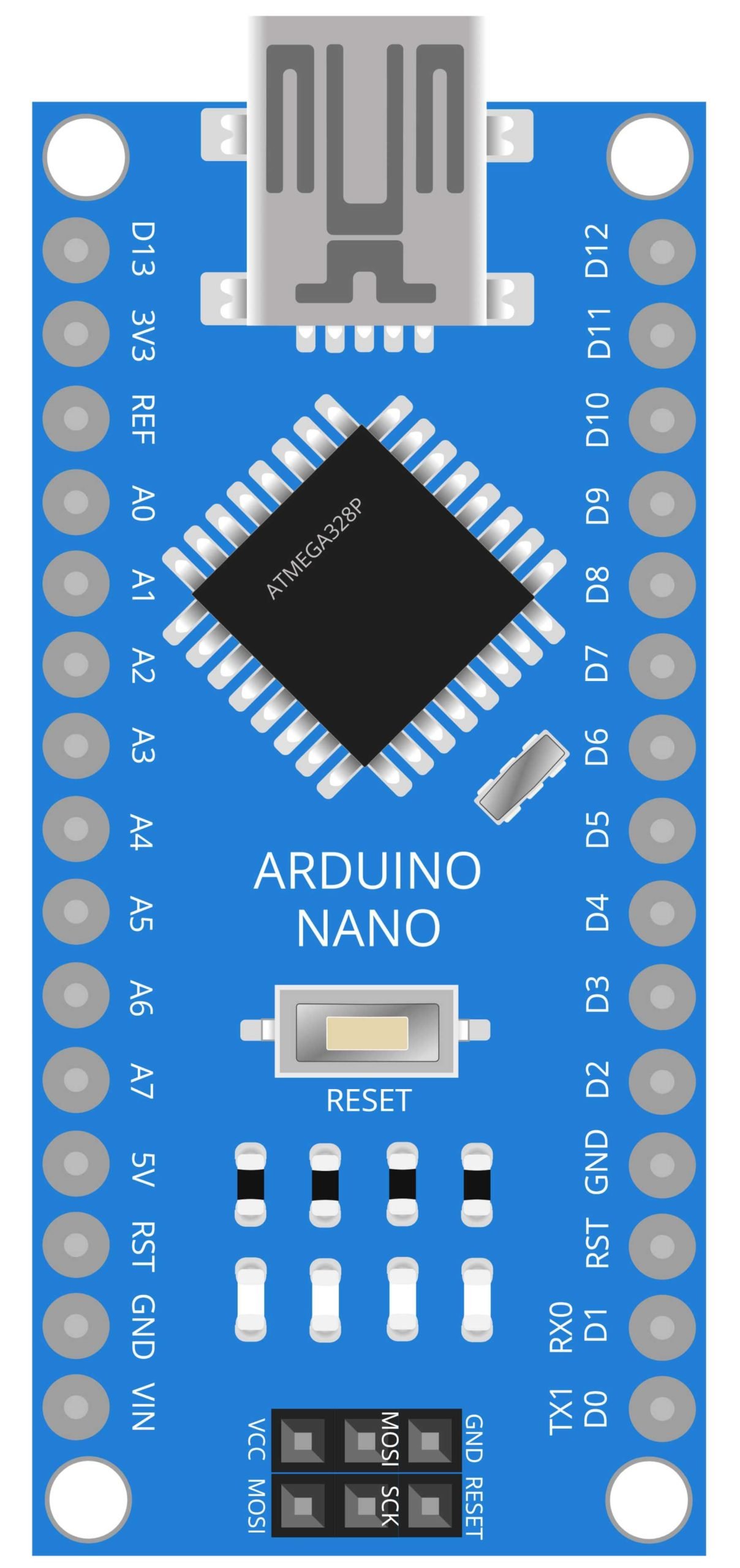
Arduino Nano
The Arduino Nano is a small, compact version of the Arduino microcontroller board. It is based on the ATmega328P microcontroller and has a similar set of digital and analog input/output pins as the Arduino UNO. It is a versatile platform for building a wide range of DIY projects and is popular among hobbyists and makers due to its small size and low cost.
In this project, the Arduino Nano acts as the brain of the system. It receives input from the flame sensor and controls the buzzer and SIM900A GSM module accordingly. The program written on the Nano is responsible for reading the sensor data and sending an SMS alert message in case of a fire. Additionally, the Nano is also responsible for controlling the buzzer, which sounds an alarm in case of a fire, and turning off the buzzer when the fire is extinguished. Overall, the Arduino Nano plays a crucial role in the functioning of the fire alarm system by controlling the various components and sending an SMS alert in case of emergency.
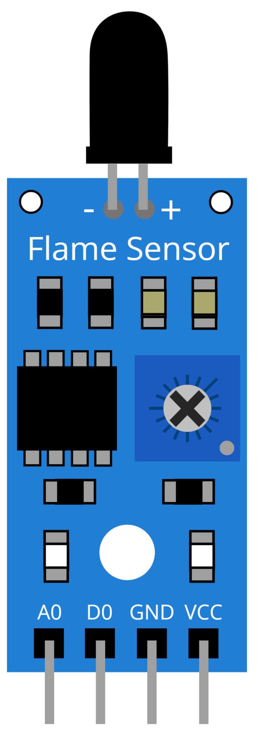
Flame Sensor
A flame sensor is a device that detects the presence of a flame or fire. It is typically used in fire alarm systems to detect the presence of a fire, and to trigger an alarm to alert people to evacuate the area. Flame sensors come in various types, including infrared, ultraviolet, and ionization sensors.
In this project, the flame sensor is used to detect the presence of a fire. The sensor sends a signal to the Arduino Nano microcontroller, which then triggers the buzzer to sound an alarm. The SIM900A GSM module is also activated to send an SMS alert to the user’s phone. This allows for quick notification of a fire even if the user is not in close proximity to the device. The use of a flame sensor in this project ensures that the fire alarm system is able to detect fires at an early stage, allowing for quick response and evacuation of the area.
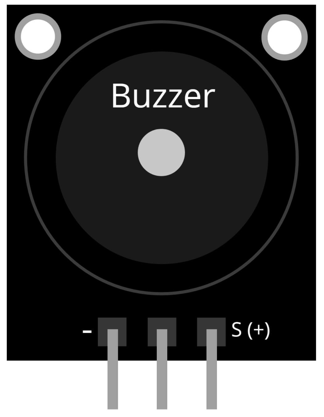
Buzzer Module
A buzzer, also known as a piezoelectric buzzer, is an electronic device that produces a sound when an alternating current is applied to it. The sound is typically a high-pitched tone and can be continuous or intermittent. Buzzers come in a variety of sizes and shapes and can be powered by a variety of sources, including batteries and mains electricity.
In this project, the buzzer is used to produce an audible alarm when the flame sensor detects a fire. The Arduino Nano controls the buzzer and sends a signal to it to sound the alarm when a fire is detected. The buzzer is an important component of the fire alarm system as it alerts the user that a fire has been detected. It serves as a warning signal to the user to take appropriate action. The use of buzzer in this project makes it easy to detect fire and take action accordingly.
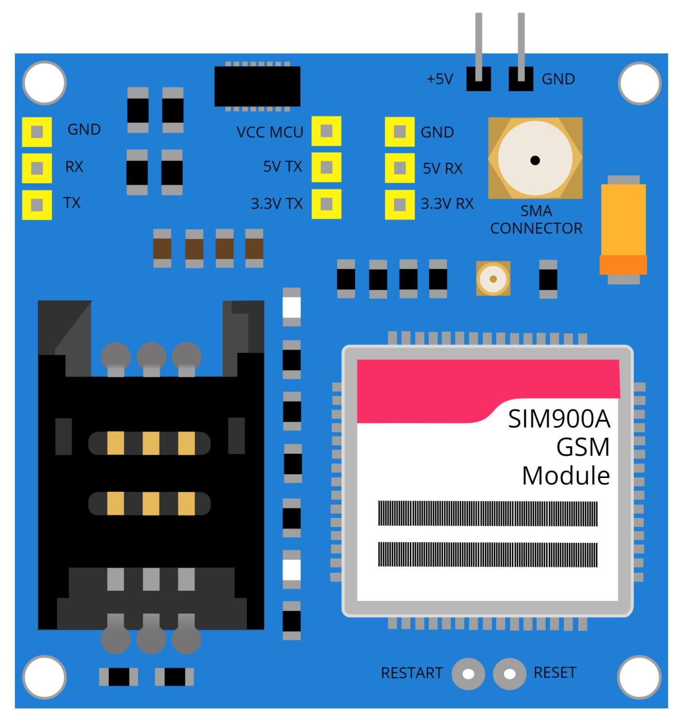
SIM900A GSM Module
The SIM900A GSM Module is a compact and powerful device that enables communication over the Global System for Mobile Communications (GSM) network. It is commonly used in various electronic projects such as home automation systems, remote control systems, and mobile-controlled robots. The SIM900A is equipped with a built-in TCP/IP stack and can be easily controlled via AT commands.
In this project, the SIM900A GSM Module is used to send an SMS to the user when the flame sensor detects a fire. The Arduino Nano, the microcontroller used in this project, communicates with the SIM900A GSM Module to send the SMS. The module is connected to the Arduino Nano using its serial communication pins. This allows the microcontroller to send and receive data from the GSM network, enabling the fire alarm to notify the user through SMS in case of a fire. This adds an extra layer of security and convenience to the project, allowing for quick notifications in case of emergency.
Steps and Info:
1. Get correct components as given. You can buy online or offline. I buy electronics components mostly from Amazon.
2. Start connecting the components. If you are new to connecting components in an electronic circuit, then use a Breadboard or you can straight up make connections using Jumper wires but it will create problem when there will be two or more connections needed at one pin (for example two or more different sensors 5V connection to Arduino’s 5V pin). But before soldering components on a PCB or printing a PCB for your circuit, better try using breadboard so that any errors and mistakes can be observed on breadboard and not after soldering. Or do connections in your way.
3. Now after building the circuit, download the Arduino IDE from https://www.arduino.cc/ website.
4. If you are new to Arduino IDE software, then watch this video we made specially for beginners about Arduino IDE.
5. If you know Arduino IDE then straight up copy the code we given and paste it into the Arduino IDE sketch.
6. Connect the Arduino to your Computer/device. Select a proper port, proper Arduino type and whatever other settings are. Here it is Arduino UNO. (If you don’t know what this all is then watch our video: ).
7. Compile the code and Upload it.
8. If any error occurs then try to troubleshoot it by finding/copy-pasting it into our Solve Errors page https://electronicsprojects.in/solve-errors/, or you can straight up paste the error on Internet and you know the rest. Also check if there are no spelling/syntax errors in the code. Compile the code again once to check if errors are fixed. I have given proper connections and code but still nothing is perfect.
9. Once code compiles and uploads smoothly, you can start testing the working of your circuit/project.
10. Keep an active SMS pack on the SIM card you are inserting the GSM module.
11. Take some fire from somewhere and show that fire to the Flame Sensor. The sensor will detect the fire and Buzzer will make sound. Along with that the GSM module will send an SMS to the phone number which you added the code.
12. If it doesn’t work, then check connections and code. Also you can talk with me and the community through discord. All the links to social is given at the right side of this page.
Program Code:
/* https://www.electronicsprojects.in : Fire Alarm using Arduino, GSM and Flame sensor */

#include <SoftwareSerial.h>
SoftwareSerial SIM900(7, 8);
String SMSTEXT;

int FlameSensor = 2;
int Buzzer = 9;

void setup() {

randomSeed(analogRead(0));
Serial.begin(9600);
SIM900.begin(9600);
Serial.println("Ready");
pinMode(FlameSensor, INPUT);
pinMode(Buzzer, OUTPUT);
digitalWrite(Buzzer, LOW);
delay(5000);

}

void loop() {


  if ( digitalRead(FlameSensor) == HIGH)
  {
  SMSTEXT =  "\nFire Detected";
  analogWrite(Buzzer, 200);
  sendSMS(SMSTEXT);
  Serial.println(SMSTEXT);
  Serial.println("Message Sent");
  delay(8000);
  }
  if ( digitalRead(FlameSensor) == LOW)
  {
  Serial.println("No Fire Detected");
  digitalWrite(Buzzer, LOW);
  delay(1000);
  }

}


void sendSMS(String message)
{
  SIM900.print("AT+CMGF=1\r");
  delay(1000);
 SIM900.println("AT + CMGS = \"+919999999999\"");  /*Add your Smart Phone Number here*/

  delay(1000);
  SIM900.println(message);
  delay(1000);
  SIM900.println((char)26);
  delay(1000);
  SIM900.println();
  delay(100);

}