Description:
This is a digital speedometer using Arduino which measures speed and fare. In this, LM393 Speed Sensor is used to detect the speed of a wheel(A wheel with bunch of holes or color mark which can be detected by the speed sensor) attached to the motor. The output can be viewed on an 16×2 LCD Display and everything is controlled using Arduino UNO.
Circuit Diagram:

Components:
| SR. NO. | COMPONENT | PINOUT DIAGRAM | BUY |
|---|---|---|---|
| 1 | Arduino UNO (Other Arduinos can be used too) | Arduino UNO Pinout Diagram⇗ | |
| 2 | LM393 Speed Sensor | ||
| 3 | 16×2 LCD Display | ||
| 4 | L298N Motor Driver | ||
| 5 | BO DC Motor with Gear Box | ||
| 6 | A wheel with holes (Check the 3D Model and Steps Section down below) | ||
| 7 | 10K Ohm Potentiometer |
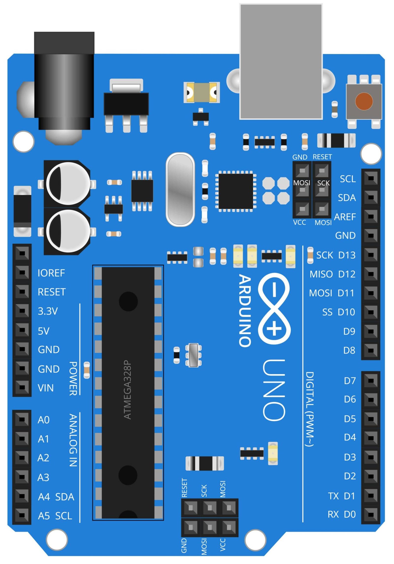
Arduino UNO
The Arduino UNO is a microcontroller board that is widely used in a variety of DIY projects, including a speedometer. It is based on the ATmega328P microcontroller and can be programmed using the Arduino IDE, which allows for easy and quick development of projects. In the context of a speedometer, the Arduino UNO is used to process signals received from the LM393 Speed Sensor and control the L298N Motor Driver. The LM393 speed sensor detects the rotation of a wheel or a shaft and sends the information to the Arduino UNO. The Arduino UNO then processes this information and calculates the speed of rotation and displays it on the 16×2 LCD display. Additionally, it is also used to control the L298N Motor Driver which is used to drive a DC motor. The Arduino UNO has a variety of input and output pins that allow it to interface with different sensors and actuators, such as the LM393 Speed Sensor and the L298N Motor Driver, which makes it an ideal solution for creating a speedometer that is accurate and easy to use.
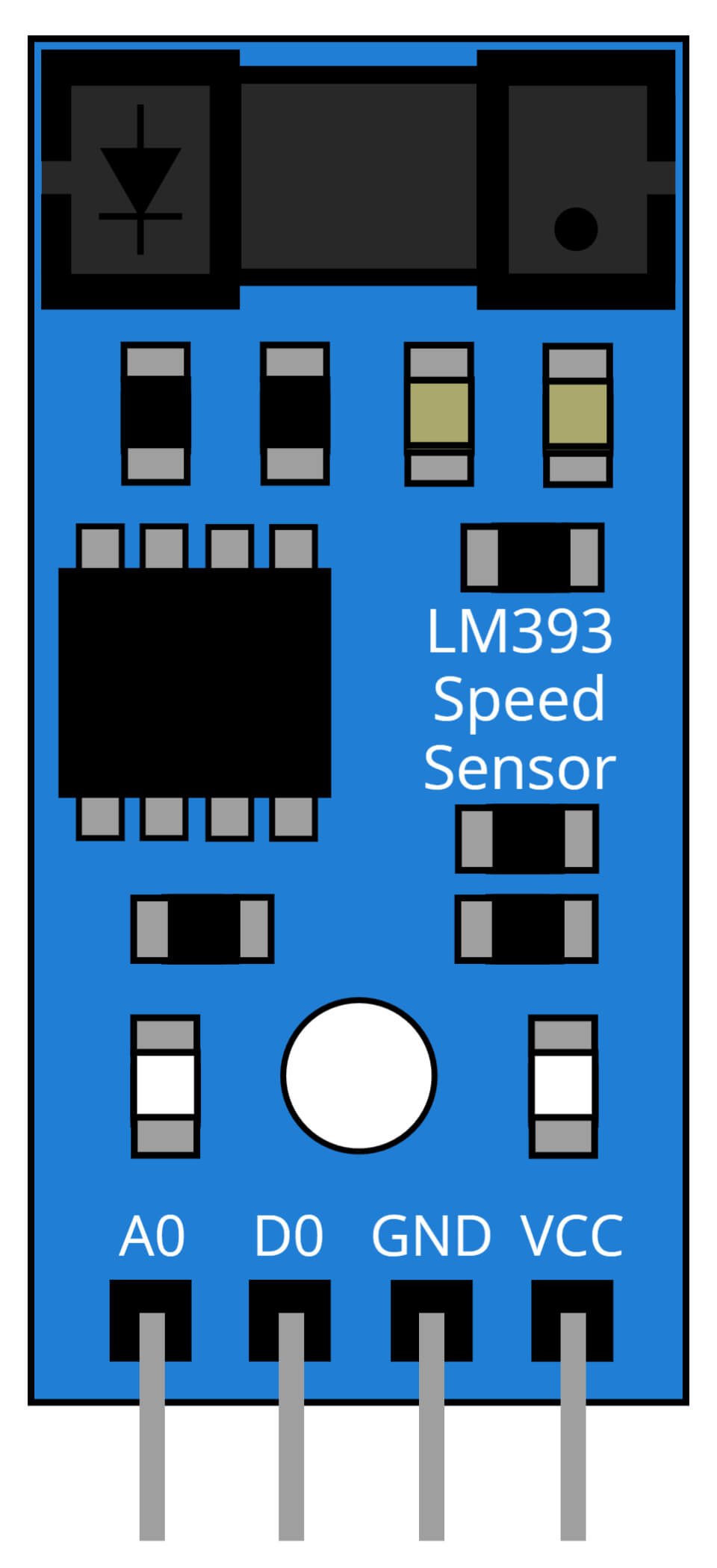
LM393 Speed Sensor
The LM393 Speed Sensor is a low-cost, high-performance sensor that is commonly used to measure the speed of rotation of a wheel or a shaft. In the context of a speedometer project, the LM393 sensor is used to detect the rotation of a wheel, and send the information to the Arduino UNO. The sensor works by outputting a square wave signal with a frequency directly proportional to the speed of rotation. The Arduino UNO then counts the number of pulses and converts it to speed, which is then displayed on the 16×2 LCD Display.
The LM393 speed sensor is highly sensitive, it can detect rotation as low as 1 RPM and it also can work with a wide range of voltage and frequency. It is also easy to interface with other devices, such as the Arduino UNO, as it sends its output via a simple digital signal. The sensor is also small and lightweight, making it easy to install in a vehicle. Additionally, it is also low power consumption making it suitable for use in vehicles where power availability is limited. The LM393 Speed Sensor is an ideal solution for creating a speedometer that is accurate, easy to use and cost-effective.
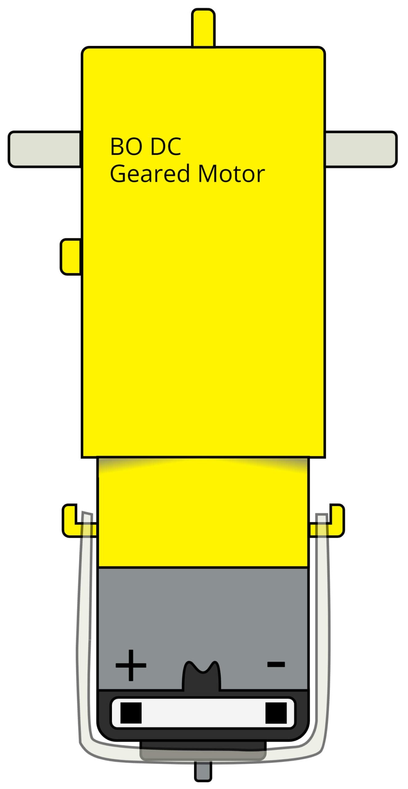
BO DC Geared Motor
BO DC geared motors are small and powerful direct current motors that are widely used in a variety of DIY projects, including speedometers. They are typically composed of a DC motor and a gear reduction transmission that allows for increased torque and reduced speed. In the context of a speedometer project, the BO DC geared motor is used to drive the wheel or shaft that the LM393 Speed Sensor is measuring. The motor is controlled by the L298N motor driver which is connected to the Arduino UNO and receive commands from it. The L298N driver is used to control the speed and direction of the motor.
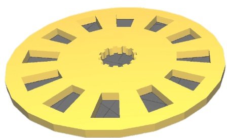
Wheel with Holes
A small wheel with holes can be made using any DIY method or simply 3D print it. I have given the 3D model STL file in ‘Downloads’ section below. As the wheel will spin, the LM393 Speed sensor can detect each hole and identify the time taken by the sensor for each hole to come and go as the wheel spins. Due to this the sensor can understand the speed of the wheel.
Steps and Info:
1. Get correct components as given. You can buy online or offline. I buy electronics components mostly from Amazon.
2. Start connecting the components. If you are new to connecting components in an electronic, circuit then use a Breadboard or you can straight up make connections using Jumper wires but it will create problem when there will be two or more connections needed at one pin(for example two or more different sensors 5V connection to Arduino’s 5V pin). But before soldering components on a PCB or printing a PCB for your circuit, better try using breadboard so that any errors and mistakes can be observed on breadboard and not after soldering. Or do connections in your way.
3. Now after building the circuit, download the Arduino IDE from https://www.arduino.cc/ website.
4. If you are new to Arduino IDE software, then watch this video we made specially for beginners about Arduino IDE.
5. If you know Arduino IDE then straight up copy the code we given and paste it into the Arduino IDE sketch.
6. Connect the Arduino to your Computer/device. Select a proper port, proper Arduino type and whatever other settings are. Here it is Arduino UNO. (If you don’t know what this all is then watch our video: ).
7. Compile the code and Upload it.
8. If any error occurs then try to troubleshoot it by finding/copy-pasting it into our Solve Errors page https://electronicsprojects.in/solve-errors/, or you can straight up paste the error on Internet and you know the rest. Also check if there are no spelling/syntax errors in the code. Compile the code again once to check if errors are fixed. I have given proper connections and code but still nothing is perfect.
9. Once code compiles and uploads smoothly, you can start testing the working of your circuit/project.
10. For this project, you will need a wheel with holes. I have given my 3D printable model in the download section. You can use it, edit it if necessary as there are two files: .stl and Google Sketchup file. If you don’t have 3D printer then you can make a wheel out of something like cardboard or plastic. Also the wheel I posted has 12 holes, so I have written 12 somewhere in the code, if your wheel has different number of holes then make sure to add that number in the code.
11. Now once the wheel is ready, attach it to the shaft of the motor and keep the wheel in between those two black sensors of LM393 Speed Sensor.
12. Observe if something pops up on the LCD, if works then cool, otherwise keep reading.
13. Check the connections and code. Also place wheel properly in the sensor. You can talk with me and the community on our discord server as well. Link to socials is given at right side of this page.
14. If your LM298N Motor Driver is not working or Motor is not spinning then attach a 12v battery to LM298N Motor Driver.
Program Code:
/* https://electronicsprojects.in Speedometer using Arduino, LM393 Speed Sensor, L298N Motor Driver and 16x2 LCD Display */

#include <LiquidCrystal.h>

int motorIn1 = 12;
int motorIn2 = 11;
int motorEnA = 13;

int encoder = 1;

volatile unsigned int counter;
int RPM;

LiquidCrystal lcd(2,3,4,5,6,7); /* If output not came then try this (7,6,5,4,3,2) */

void setup() {
  pinMode(motorIn1, OUTPUT);
  pinMode(motorIn2, OUTPUT);
  pinMode(motorEnA, OUTPUT);
  pinMode(encoder, INPUT);

  digitalWrite(encoder, HIGH);
  digitalWrite(motorIn1, HIGH);
  digitalWrite(motorIn2, LOW);
  analogWrite(motorEnA, 100);

  attachInterrupt(0,countpulse,RISING);
  lcd.begin(16, 2);
}

void countpulse(){
        counter++;
}

void loop() {
  static uint32_t previousMillis;
  if (millis() - previousMillis >= 1000) {
            RPM = (counter/12)*60;       /* Here my wheel has 12 holes so counter/12, i have written 12, if you use my wheel model then okay otherwise you can change that 12 and write your own wheel's number of holes */
            counter = 0;
            previousMillis += 1000;
  }

  lcd.setCursor(0,0);
  lcd.print("Speed: ");
  lcd.setCursor(7,0);
  lcd.print(RPM);
  lcd.print(" rps");
  delay(1);
}