Description:
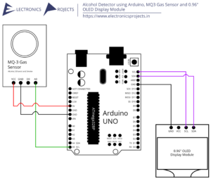
In this project we are building a Restauran Menu Ordering System using Arduino. This menu system can be used for ordering food in restaurants along with calling for server/waiter and bill. In this a TFT Display Shield for Arduino UNO is used, it is touch display and has the menu displayed on it. A person can choose the food item and send the order to the kitchen or whatever it is. A buzzer is attached to the kitchen side and goes brrrrrr when any order or command is received. RF Transmitter and Receiver is used for communication. Arduino UNO and Arduino Nano is used.
Circuit Diagram:


Components:
| SR. NO. | COMPONENT | PINOUT DIAGRAM | BUY |
|---|---|---|---|
| 1 | Arduino UNO | Arduino UNO Pinout Diagram⇗ | |
| 2 | Arduino Nano (Here, other Arduinos can be used too) | ||
| 3 | TFT Display Shield for Arduino UNO | ||
| 4 | 433Mhz FS1000A RF Transmitter | ||
| 5 | 433Mhz XY-Mk-5V RF Receiver | ||
| 6 | Buzzer | ||
| 7 | 16×2 LCD Display | ||
| 8 | I2C Module for 16×2 LCD Display |
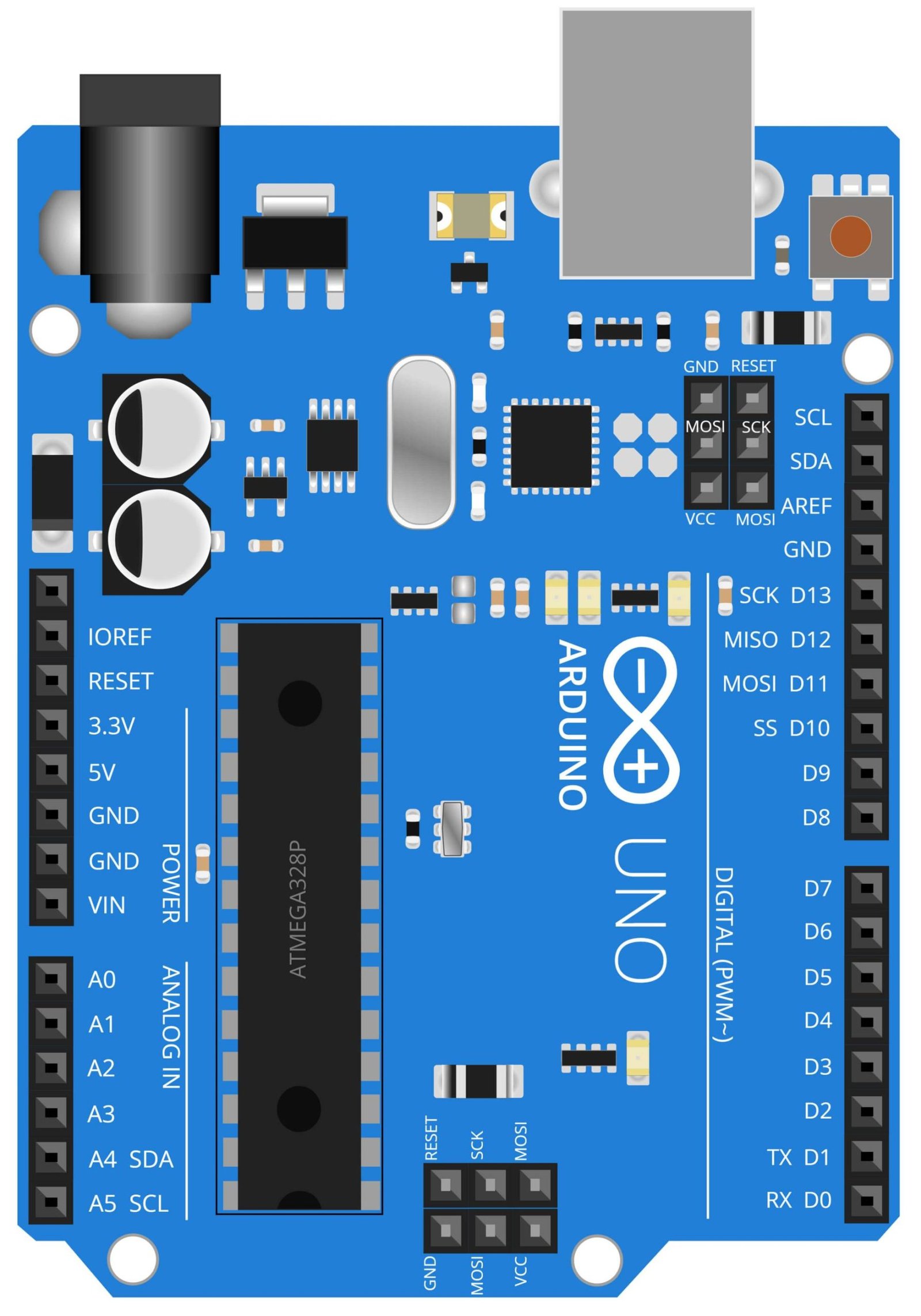
Arduino UNO
The Arduino UNO is a microcontroller board based on the ATmega328P. It is an open-source platform that allows for easy programming and prototyping of electronic projects. In this project, the Arduino UNO serves as the brain of the transmitter circuit. It controls the TFT display and FS1000A RF transmitter. The TFT display is used to show the menu items, and the RF transmitter is used to send the order data wirelessly to the receiver circuit. The Arduino UNO is programmed to receive input from the TFT display and send it to the RF transmitter to transmit the order data. The Arduino UNO’s flexibility and ease of use make it a great choice for this type of project, and similar projects in the field of IoT and home automation. The use of Arduino UNO provides a simple and efficient way to control the display and wireless communication in this project.
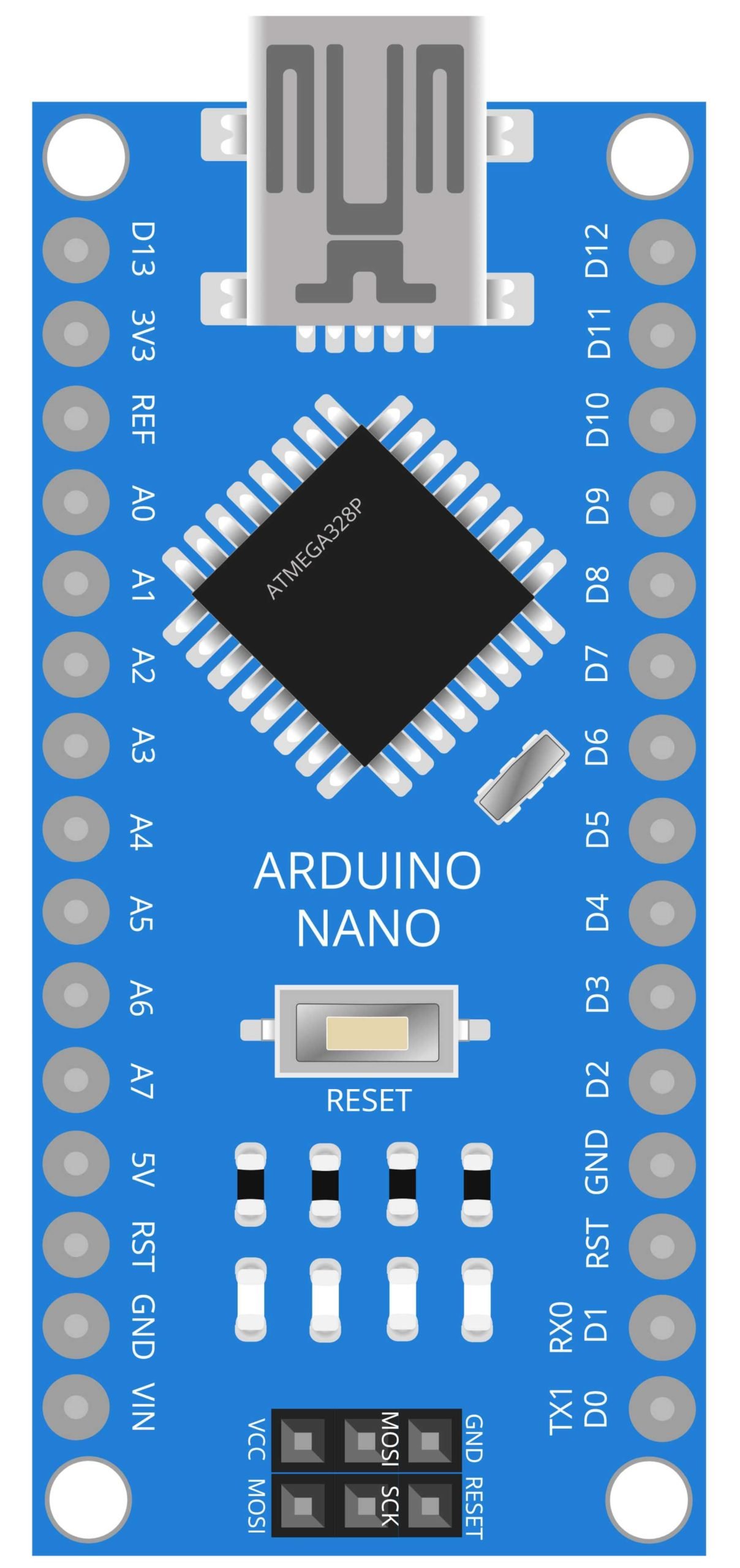
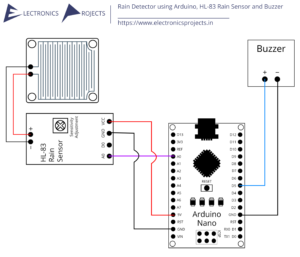
Arduino Nano
The Arduino Nano is a compact and breadboard-friendly version of the Arduino UNO microcontroller board. It is based on the ATmega328P microcontroller and can be powered by USB or an external power supply. In this project, the Arduino Nano serves as the brain of the receiver circuit. It controls the 16×2 LCD display, the XY-MK-5V RF Receiver, the buzzer, and the I2C module for the 16×2 LCD display. The receiver circuit receives the order data from the transmitter circuit through the RF receiver and displays it on the LCD display using the I2C module. The Arduino Nano also triggers the buzzer to alert the staff when an order is received. The compact size and low power consumption of the Arduino Nano makes it a great choice for portable or battery-powered projects. The Arduino Nano can also be used in embedded systems, robotics and other IoT projects.

FS1000A RF Transmitter
The FS1000A RF Transmitter is a small, low-cost wireless device that operates at a frequency of 433 MHz. It is designed to transmit digital data, such as on/off signals, over short distances. In this project, the FS1000A RF transmitter is used to wirelessly transmit the order data from the transmitter circuit to the receiver circuit. The transmitter is connected to the Arduino UNO microcontroller and the TFT display, which is used to show the menu items. The Arduino UNO is programmed to receive input from the TFT display and send it to the FS1000A RF transmitter to transmit the order data. The FS1000A RF Transmitter is a cost-effective solution that allows for wireless communication without the need for a wired connection, making it easier to install and maintain. The FS1000A RF Transmitter’s low power consumption and long range transmission capability makes it a suitable for IoT and home automation projects.

XY-MK-5V RF Receiver
The XY-MK-5V RF Receiver is a small, low-cost wireless device that operates at a frequency of 433 MHz. It is designed to receive digital data, such as on/off signals, over short distances. In this project, the XY-MK-5V RF Receiver is used to wirelessly receive the order data from the transmitter circuit. The receiver is connected to the Arduino Nano microcontroller and the 16×2 LCD Display. The Arduino Nano is programmed to receive the order data from the RF receiver and display it on the LCD display using the I2C module. The XY-MK-5V RF Receiver is a cost-effective solution that allows for wireless communication without the need for a wired connection, making it easier to install and maintain. The XY-MK-5V RF Receiver’s low power consumption and long range reception capability makes it a suitable for IoT and home automation projects. In this project, it receives the order data from the transmitter circuit, and then triggers the buzzer to alert the staff when an order is received.

Buzzer
A buzzer is an electromechanical device that produces sound when an electrical current is passed through it. In this project, the buzzer is used in the receiver circuit to alert the staff when an order is received. The buzzer is connected to the Arduino Nano microcontroller, which is programmed to trigger the buzzer to make a sound when the order data is received by the XY-MK-5V RF Receiver. This feature allows the staff to be immediately alerted when an order is placed, ensuring that orders are processed and prepared quickly. The buzzer can be adjusted to make different types of sounds, such as a beep or a melody, to indicate the type of order or priority level. Additionally, the use of a buzzer eliminates the need for a dedicated staff member to monitor the orders as they come in and eliminates the need for a visual indicator. This feature makes the system more efficient and cost-effective.
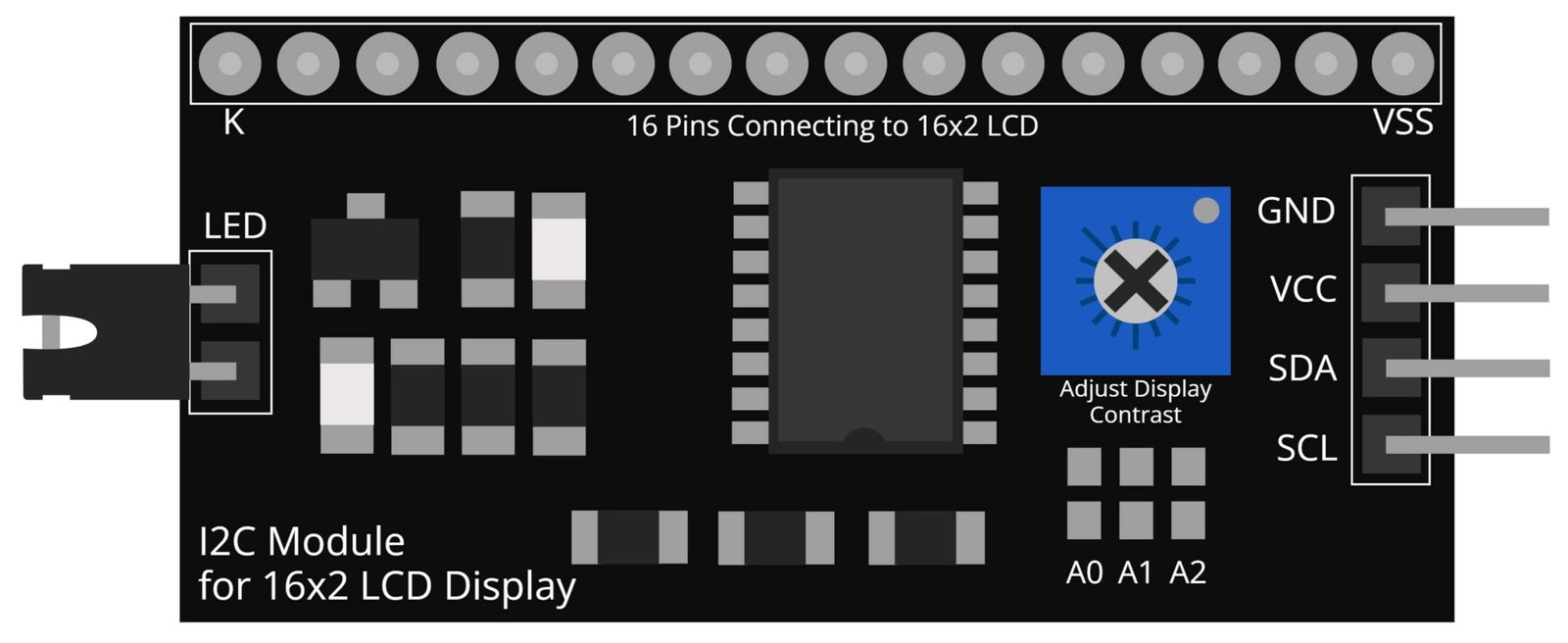
I2C Module for 16×2 LCD Display
The I2C Module for 16×2 LCD Display is an electronic device that connects to an LCD display using the I2C communication protocol. I2C is a serial communication protocol that enables multiple devices to communicate with one another using just two wires: SDA (Serial Data) and SCL (Serial Clock). In this project, the I2C module is used to connect the 16×2 LCD display to the Arduino Nano microcontroller in the receiver circuit. The module allows the Arduino Nano to communicate with the LCD display and display the order data received from the RF receiver. The I2C module simplifies the connection between the Arduino Nano and the LCD display as it only requires two wires for communication and eliminates the need for multiple wires. Additionally, it also reduces the number of pins required on the Arduino Nano, making it ideal for projects with limited pin resources.
Steps and Info:
1. Get correct components as given. You can buy online or offline. I buy electronics components mostly from Amazon.
2. Start connecting the components. If you are new to connecting components in an electronic circuit, then use a Breadboard or you can straight up make connections using Jumper wires but it will create problem when there will be two or more connections needed at one pin (for example two or more different sensors 5V connection to Arduino’s 5V pin). But before soldering components on a PCB or printing a PCB for your circuit, better try using breadboard so that any errors and mistakes can be observed on breadboard and not after soldering. Or do connections in your way.
3. Now after building the circuit, download the Arduino IDE from https://www.arduino.cc/ website.
4. If you are new to Arduino IDE software, then watch this video we made specially for beginners about Arduino IDE.
5. If you know Arduino IDE then straight up copy the code we given and paste it into the Arduino IDE sketch. You will need to manually install few libraries in the Arduino IDE software. Links to the libraries given below in Links section.
6. Connect the Arduino to your Computer/device. Select a proper port, proper Arduino type and whatever other settings are. Here it is Arduino UNO. (If you don’t know what this all is then watch our video: ).
7. Compile the code and Upload it.
8. If any error occurs then try to troubleshoot it by finding/copy-pasting it into our Solve Errors page https://electronicsprojects.in/solve-errors/, or you can straight up paste the error on Internet and you know the rest. Also check if there are no spelling/syntax errors in the code. Compile the code again once to check if errors are fixed. I have given proper connections and code but still nothing is perfect.
9. Once code compiles and uploads smoothly, you can start testing the working of your circuit/project.
10. Once both transmitter and receiver circuits are ready, turn them ON using the USB to your device/powerbank or connect 12v Battery or 12v 1amp charger.
11. On transmitter circuit, a menu will show up on the TFT Display, start choosing the food, calling waiter or bill and check if the buzzer makes sound on the receiver circuit.
12. If it doesn’t then check connections and code. Also you can talk with me and the community through discord. All the links to social is given at the right side of this page.
Program Code:
Transmitter Circuit Code:
/* https://www.electronicsprojects.in Restaurant Menu Ordering System using Arduino, TFT Display, 433Mhz RF Transmitter and Receiver */

/* Transmitter Circuit Code */

#include <RH_ASK.h>
#include <SPI.h>
#include <SPFD5408_Adafruit_GFX.h>
#include <SPFD5408_Adafruit_TFTLCD.h>
#include <SPFD5408_TouchScreen.h>
const char *msg ;
RH_ASK driver;
#define YP A1
#define XM A2
#define YM 7
#define XP 6
#define TS_MINX 125
#define TS_MINY 85
#define TS_MAXX 965
#define TS_MAXY 905
TouchScreen ts = TouchScreen(XP, YP, XM, YM, 300);
#define LCD_CS A3
#define LCD_CD A2
#define LCD_WR A1
#define LCD_RD A0
#define LCD_RESET A4
#define REDBAR_MINX 80
#define GREENBAR_MINX 130
#define BLUEBAR_MINX 180
#define BAR_MINY 30
#define BAR_HEIGHT 250
#define BAR_WIDTH 30
Adafruit_TFTLCD tft(LCD_CS, LCD_CD, LCD_WR, LCD_RD, LCD_RESET);
#define BLACK   0x0000
int BLUE = tft.color565(50, 50, 255);
#define DARKBLUE 0x0010
#define VIOLET 0x8888
#define RED     0xF800
#define GREEN   0x07E0
#define CYAN    0x07FF
#define MAGENTA 0xF81F
#define YELLOW  0xFFE0
#define WHITE   0xFFFF
#define WARM_WHITE   tft.color565(239, 235, 216);
#define GOLD 0xFEA0
#define BROWN 0xA145
#define SILVER 0xC618
#define LIME 0x07E0
void drawHome()
{
  tft.fillScreen(WHITE);
  tft.drawRoundRect(0, 0, 319, 240, 8, WHITE);
  tft.fillRoundRect(30, 40, 100, 40, 8, GOLD);
  tft.drawRoundRect(30, 40, 100, 40, 8, WHITE);
  tft.fillRoundRect(30, 90, 100, 40, 8, GOLD);
  tft.drawRoundRect(30, 90, 100, 40, 8, WHITE);
  tft.fillRoundRect(30, 140, 100, 40, 8, GOLD);
  tft.drawRoundRect(30, 140, 100, 40, 8, WHITE);
  tft.fillRoundRect(10, 190, 190, 40, 8, CYAN);
  tft.drawRoundRect(10, 190, 190, 40, 8, WHITE);
  tft.fillRoundRect(180, 40, 100, 40, 8, GOLD);
  tft.drawRoundRect(180, 40, 100, 40, 8, WHITE);
  tft.fillRoundRect(180, 90, 100, 40, 8, GOLD);
  tft.drawRoundRect(180, 90, 100, 40, 8, WHITE);
  tft.fillRoundRect(180, 140, 100, 40, 8, GOLD);
  tft.drawRoundRect(180, 140, 100, 40, 8, WHITE);
  tft.fillRoundRect(210, 190, 100, 40, 8, GREEN);
  tft.drawRoundRect(210, 190, 100, 40, 8, WHITE);
  tft.setCursor(60, 0);
  tft.setTextSize(3);
  tft.setTextColor(LIME);
  tft.print(" Food Menu");
  tft.setTextSize(2);
  tft.setTextColor(WHITE);
  tft.setCursor(37, 47);
  tft.print(" nuts");
  tft.setCursor(37, 97);
  tft.print(" crabs");
  tft.setCursor(37, 147);
  tft.print(" crumbs");
  tft.setCursor(23, 197);
  tft.print(" Call Server");
  tft.setCursor(187, 47);
  tft.print(" peas");
  tft.setCursor(187, 97);
  tft.print(" potion");
  tft.setCursor(187, 147);
  tft.print(" med kit");
  tft.setCursor(227, 197);
  tft.print(" Bill");
}
int oldcolor, currentcolor, currentpcolour;
void setup(void) {
  tft.reset();
  tft.begin(tft.readID());
  Serial.begin(9600);
  Serial.println();
  Serial.print("reading id...");
  delay(500);
  Serial.println(tft.readID(), HEX);
  tft.fillScreen(BLACK);
  tft.setRotation(1);
  tft.setTextSize(3);
  tft.setTextColor(WHITE);
  tft.setCursor(50, 140);
  tft.print("sup !, wait...");
  tft.setTextColor(tft.color565(255, 255, 0));
  for (int i; i < 250; i++)
  {
    tft.fillRect(BAR_MINY - 10, BLUEBAR_MINX, i, 10, RED);
    delay(0.000000000000000000000000000000000000000000000000001);
  }
  tft.fillScreen(BLACK);
  if (!driver.init())
      Serial.println("bad move");
  drawHome();
  pinMode(13, OUTPUT);
}
#define MINPRESSURE 10
#define MAXPRESSURE 1000
void transmit()
{
  driver.send((uint8_t *)msg, strlen(msg));
  driver.waitPacketSent();
  delay(1000);
  }
void loop()
{
  digitalWrite(13, HIGH);
  TSPoint p = ts.getPoint();
  digitalWrite(13, LOW);
  pinMode(XM, OUTPUT);
  pinMode(YP, OUTPUT);
  if (p.z > ts.pressureThreshhold)
    {
      p.x = map(p.x, TS_MAXX, TS_MINX, 0, 320);
      p.y = map(p.y, TS_MAXY, TS_MINY, 0, 240);
      if (p.x > 180 && p.x < 280 && p.y > 190 && p.y < 230  && p.z > MINPRESSURE && p.z < MAXPRESSURE)
      {
        Serial.println("nuts");
        msg = "nuts Ordered";
        transmit();
        tft.fillRoundRect(30, 40, 100, 40, 8, WHITE);
        delay(70);
        tft.fillRoundRect(30, 40, 100, 40, 8, GOLD);
        tft.drawRoundRect(30, 40, 100, 40, 8, WHITE);
        tft.setCursor(37, 47);
        tft.println(" nuts");
        delay(70);
        }
      if (p.x > 180 && p.x < 280 && p.y > 140 && p.y < 180)
      {
        Serial.println("crabs");
        msg = "crabs Ordered";
        transmit();
        tft.fillRoundRect(30, 90, 100, 40, 8, WHITE);
        delay(70);
        tft.fillRoundRect(30, 90, 100, 40, 8, GOLD);
        tft.drawRoundRect(30, 90, 100, 40, 8, WHITE);
        tft.setCursor(37, 97);
        tft.println(" crabs");
        delay(70);
      }
      if (p.x > 180 && p.x < 280 && p.y > 90 && p.y < 130)
      {
        Serial.println("crumbs");
        msg = "crumbs Ordered";
        transmit();
        tft.fillRoundRect(30, 140, 100, 40, 8, WHITE);   //rgb led
        delay(70);
        tft.fillRoundRect(30, 140, 100, 40, 8, GOLD);   //rgb led
        tft.drawRoundRect(30, 140, 100, 40, 8, WHITE);   //rgb led
        tft.setCursor(37, 147);
        tft.print(" crumbs");
        delay(70);
      }
      if (p.x > 210 && p.x < 310 && p.y > 40 && p.y < 80)
      {
        Serial.println("Call Server");
        msg = "Calling Server";
        transmit();
        tft.fillRoundRect(10, 190, 190, 40, 8, WHITE);
        delay(70);
        tft.fillRoundRect(10, 190, 190, 40, 8, CYAN);
        tft.drawRoundRect(10, 190, 190, 40, 8, WHITE);
        tft.setCursor(23, 197);
        tft.print(" Call Server");
        delay(70);
      }
      if (p.x > 30 && p.x < 130 && p.y > 190 && p.y < 230)
      {
        Serial.println("peas");
        msg = "peas Ordered";
        transmit();
        tft.fillRoundRect(30, 40, 100, 40, 8, WHITE);
        delay(70);
        tft.fillRoundRect(30, 40, 100, 40, 8, GOLD);
        tft.drawRoundRect(30, 40, 100, 40, 8, WHITE);
        tft.setCursor(187, 47);
        tft.print(" peas");
        delay(70);
      }
      if (p.x > 30 && p.x < 130 && p.y > 140 && p.y < 180 )
      {
        Serial.println("potion");
        msg = "potion Ordered";
        transmit();
        tft.fillRoundRect(180, 90, 100, 40, 8, WHITE);
        delay(70);
        tft.fillRoundRect(180, 90, 100, 40, 8, GOLD);
        tft.drawRoundRect(180, 90, 100, 40, 8, WHITE);
        tft.setCursor(187, 97);
        tft.print(" potion");
        delay(70);
      }
      if (p.x > 30 && p.x < 130 && p.y > 90 && p.y < 130)
      {
        Serial.println("med kit");
        msg = "med kit Ordered";
        transmit();
        tft.fillRoundRect(180, 140, 100, 40, 8, WHITE);
        delay(70);
        tft.fillRoundRect(180, 140, 100, 40, 8, GOLD);
        tft.drawRoundRect(180, 140, 100, 40, 8, WHITE);
        tft.setCursor(187, 147);
        tft.print(" med kit");
        delay(70);
      }
      if (p.x > 10 && p.x < 210 && p.y > 40 && p.y < 80)
      {
        Serial.println("Bill");
        msg = "The Bill";
        transmit();
        tft.fillRoundRect(210, 190, 100, 40, 8, WHITE);
        delay(70);
        tft.fillRoundRect(210, 190, 100, 40, 8, GREEN);
        tft.drawRoundRect(210, 190, 100, 40, 8, WHITE);
        tft.setCursor(227, 197);
        tft.print(" Bill");
        delay(70);
      }
    }
}
Receiver Circuit Code:
 /* https://www.electronicsprojects.in Restaurant Menu Ordering System using Arduino, TFT Display, 433Mhz RF Transmitter and Receiver */

/* Receiver Circuit Code */

#include <RH_ASK.h>
#include <SPI.h> // Not actualy used but needed to compile
#include <LiquidCrystal_I2C.h>
//String msg;
LiquidCrystal_I2C lcd(0x27, 16, 2);
RH_ASK driver;
#define buzzer 2
void setup()
{
    Serial.begin(9600);  // Debugging only
    pinMode(buzzer, OUTPUT);
    lcd.begin(16,2);
    lcd.clear();
    if (!driver.init())
         Serial.println("init failed");
}
void loop()
{
    uint8_t buf[17];
    uint8_t buflen = sizeof(buf);
    if (driver.recv(buf, &buflen)) // Non-blocking
    {
      int i;
      digitalWrite(buzzer, HIGH);
      delay(1000);
      digitalWrite(buzzer, LOW);
      // Message with a good checksum received, dump it.
      Serial.print("Message: ");
      Serial.println((char*)buf);
      lcd.clear();
      lcd.setCursor(0,0);
      lcd.print("T1:");
      lcd.print((char*)buf);
    }
}
Download:
Links:
Libraries:
RadioHead Master Library: https://github.com/PaulStoffregen/RadioHead
SPFD5408 Library: https://github.com/JoaoLopesF/SPFD5408