Description:
In this project we build LPG and Smoke Detector using Arduino and MQ2 Gas Sensor. Here, the MQ2 Gas Sensor is used to detect Smoke, LPG, Methane and Butane. When the gas is detected the LED glows and Buzzer makes sound. Everything is controlled using Arduino UNO.
Circuit Diagram:
")
Components:
| SR. NO. | COMPONENT | PINOUT DIAGRAM | BUY |
|---|---|---|---|
| 1 | Arduino UNO (Other Arduinos can be used too) | Arduino UNO Pinout Diagram⇗ | |
| 2 | Buzzer | ||
| 3 | Red LED | ||
| 4 | Green LED | ||
| 5 | MQ2 Gas Sensor | MQ2 Gas Sensor Pinout Diagram⇗ | |
| 6 | 220 Ohm Resistor x 2 |
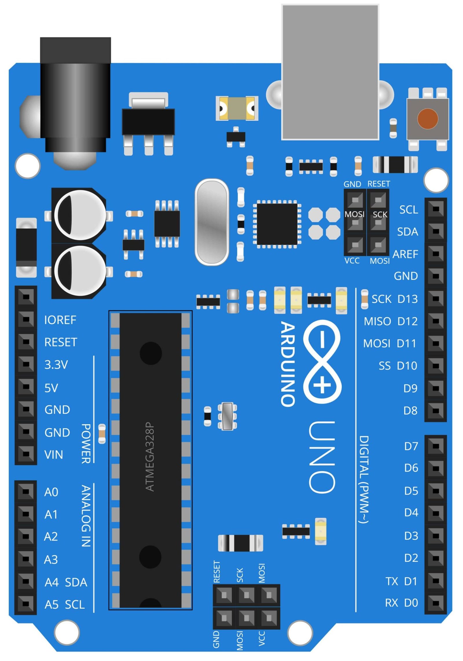
Arduino UNO
Arduino UNO is a microcontroller board based on the ATmega328P. It has 14 digital input/output pins, 6 analog inputs, a 16 MHz quartz crystal, a USB connection, a power jack, an ICSP header, and a reset button. The board is equipped with sets of digital and analog input/output (I/O) pins that may be interfaced to various expansion boards and other circuits. The board can be powered by USB cable or by an external 9 volt battery, though it accepts voltages between 7 and 20 volts.
In this project, the Arduino UNO serves as the brain of the system. It reads the data from the MQ2 gas sensor and controls the buzzer, red LED, and green LED. The 220 Ohm resistor is used to provide the appropriate amount of current to the LEDs. The Arduino UNO also communicates with the 16×2 LCD display to show the status of the system whether it is detecting smoke or LPG gas. The code for the system is uploaded to the Arduino UNO using a USB cable.
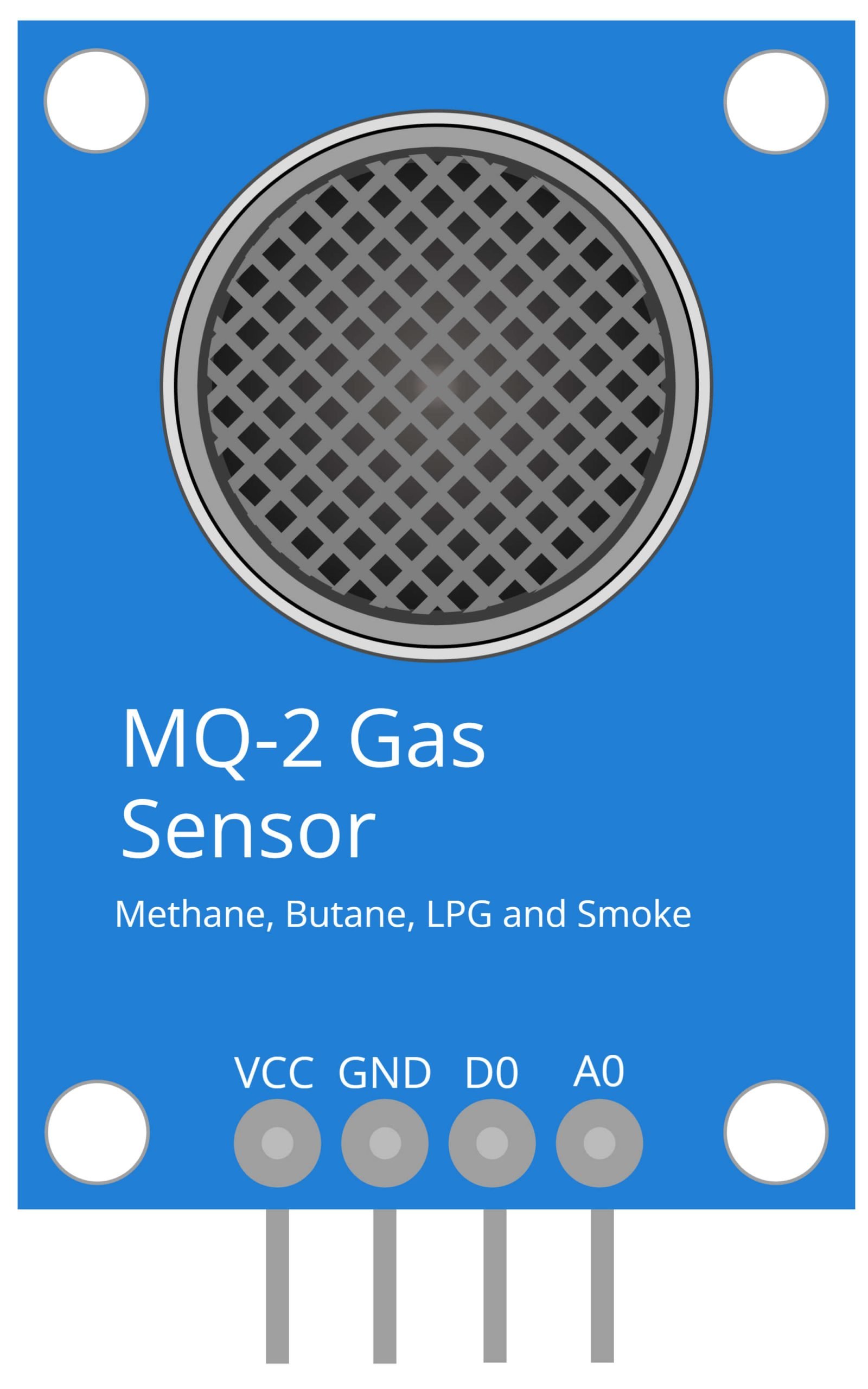
MQ2 Gas Sensor
The MQ2 gas sensor is a widely used sensor for detecting a variety of gases, including propane, methane, and smoke. It is a low cost sensor that is sensitive to a wide range of gases and is often used in gas leakage detection systems. It is a simple to use device that can be easily interfaced with microcontrollers such as the Arduino UNO.
In this project, the MQ2 gas sensor is used to detect the presence of LPG and smoke in the air. The sensor is connected to the Arduino UNO microcontroller, which reads the sensor’s output and triggers an alarm in the form of a buzzer and flashing red LED if dangerous levels of gas are detected. The green LED is used to indicate normal operation, and the 220 ohm resistor is used to limit the current flowing through the LED’s. The 16×2 LCD display is used to show the status of the system.

Red LED
A light-emitting diode (LED) is a semiconductor light source that emits light when an electric current is passed through it. Red LEDs are a common type of LED and are used in a wide range of applications, including indicator lights, automotive lighting, and electronic displays. They are known for their bright, long-lasting light and low power consumption.
In this project, the red LED is used as an indicator to alert the user of potential gas leaks or smoke. When the MQ2 gas sensor detects an abnormal level of LPG or smoke, the Arduino UNO board sends a signal to the red LED to turn on, alerting the user to take action. This feature serves as an added safety measure to ensure that the user is aware of any potential gas leaks or smoke in the area.

Green LED
The 220 Ohm resistor is a passive electronic component that is widely used in electronic circuits to control the flow of electrical current. It is a fixed value resistor that is made up of a ceramic or metal oxide material. The resistance value of a 220 Ohm resistor is marked with colored bands on its body.
In this project, the 220 Ohm resistor is used to limit the current flowing through the LEDs, which are used as indicators in the project. The 220 Ohm resistor is connected in series with the LEDs to prevent them from burning out due to excessive current. The resistor ensures that the correct amount of current flows through the LEDs, making them bright enough to be easily visible while also prolonging their lifespan.

Buzzer
A buzzer, also known as an audible alarm, is an electronic device that makes a loud noise when activated. They are commonly used in a wide range of applications including alarms, timers, and warning signals. Buzzers can be classified into two types: mechanical and solid-state. Mechanical buzzers use a diaphragm that vibrates to produce sound, while solid-state buzzers use electronic oscillation to produce sound.
In this project, the buzzer is used as an alarm system. The buzzer is activated when the MQ2 gas sensor detects a certain level of LPG or smoke. The 220 Ohm resistor is used to control the current flowing through the buzzer and the red LED is used to indicate that the alarm is sounding. The green LED is used to indicate that the system is working properly. In this way, the buzzer plays a critical role in alerting the user to the presence of dangerous gases.

Resistor
A resistor is an electronic component that resists the flow of electric current. The 220 Ohm resistor, specifically, is a commonly used resistor value that is often used to reduce or limit the amount of current flowing through a circuit.
In this project, the 220 Ohm resistor is used in conjunction with the Red LED and the Green LED. The resistor is placed in series with the LEDs to limit the current flowing through them, and thus controlling the brightness of the LEDs. When the MQ2 gas sensor detects smoke or LPG gas, the Arduino UNO sends a signal to either turn on the Red LED, indicating a smoke or LPG gas detection, or turn on the Green LED, indicating safe air quality.
Steps and Info:
1. Get correct components as given. You can buy online or offline. I buy electronics components mostly from Amazon.
2. Start connecting the components. If you are new to connecting components in an electronic circuit, then use a Breadboard or you can straight up make connections using Jumper wires but it will create problem when there will be two or more connections needed at one pin (for example two or more different sensors 5V connection to Arduino’s 5V pin). But before soldering components on a PCB or printing a PCB for your circuit, better try using breadboard so that any errors and mistakes can be observed on breadboard and not after soldering. Or do connections in your way.
3. Now after building the circuit, download the Arduino IDE from https://www.arduino.cc/ website.
4. If you are new to Arduino IDE software, then watch this video we made specially for beginners about Arduino IDE.
5. If you know Arduino IDE then straight up copy the code we given and paste it into the Arduino IDE sketch.
6. Connect the Arduino to your Computer/device. Select a proper port, proper Arduino type and whatever other settings are. Here it is Arduino UNO. (If you don’t know what this all is then watch our video: ).
7. Compile the code and Upload it.
8. If any error occurs then try to troubleshoot it by finding/copy-pasting it into our Solve Errors page https://electronicsprojects.in/solve-errors/, or you can straight up paste the error on Internet and you know the rest. Also check if there are no spelling/syntax errors in the code. Compile the code again once to check if errors are fixed. I have given proper connections and code but still nothing is perfect.
9. Once code compiles and uploads smoothly, you can start testing the working of your circuit/project.
10. Now take any of these (Smoke, LPG, Methane and Butane) near the MQ2 Gas sensor. When the sensor detects any of the gases mentioned, the LED will glow and Buzzer will make sound.
11. If it doesn’t work, then check connections and code. Also you can talk with me and the community through discord. All the links to social is given at the right side of this page.
Program Code:
/* https://www.electronicsprojects.in LPG and Smoke Detector using Arduino and MQ2 Gas Sensor. (Detects Methane and Butane as well) */

int REDLED = 11;
int GREENLED = 10;
int BUZZER = 10;
int MQ2 = A5;
int MQ2THRESHOLD = 400;
void setup() {
  pinMode(REDLED, OUTPUT);
  pinMode(GREENLED, OUTPUT);
  pinMode(BUZZER, OUTPUT);
  pinMode(MQ2, INPUT);
  Serial.begin(9600);
}
void loop() {
  int MQ2SENSOR = analogRead(MQ2);
  if (MQ2SENSOR > MQ2THRESHOLD)
  {
    digitalWrite(REDLED, HIGH);
    digitalWrite(GREENLED, LOW);
    tone(BUZZER, 1000, 200);
  }
  else
  {
    digitalWrite(REDLED, LOW);
    digitalWrite(GREENLED, HIGH);
    noTone(BUZZER);
  }
delay(69);
}