Description:
In this project we build a Pedometer using Arduino which detects and counts steps you taken while walking or jogging. Steps are detected using ADXL335 Accelerometer sensor when there is tilt in the axis of the sensor. Steps can be seen on 16×2 LCD Display and everything is controlled using Arduino Nano.
Circuit Diagram:
 using Arduino, ADXL335 Accelerometer Sensor and 16x2 LCD Display")
Components:
| SR. NO. | COMPONENT | PINOUT DIAGRAM | BUY |
|---|---|---|---|
| 1 | Arduino Nano (Other Arduinos can be used too) | ||
| 2 | 16×2 LCD Display | ||
| 3 | ADXL335 Accelerometer Sensor | ||
| 4 | I2C Module for 16×2 LCD Display |
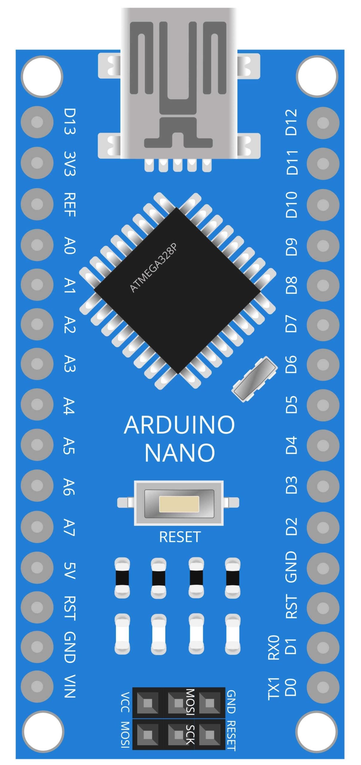
Arduino Nano
The Arduino Nano is a small, breadboard-friendly development board based on the ATmega328P microcontroller. It has 14 digital input/output pins, 8 analog inputs, a 16 MHz quartz crystal, a USB connection, and a power jack. The compact size and ease of use of the Nano make it a popular choice for DIY projects and hobbyists.
In this project, the Arduino Nano serves as the brain of the device, processing data from the ADXL335 accelerometer sensor and controlling the 16×2 LCD display. The accelerometer sensor detects the movement of the person wearing the device and sends the data to the Nano, which then uses an algorithm to calculate the number of steps taken. The Nano then displays the number of steps on the LCD display. One of the main advantages of using an Arduino Nano in this project is its compact size and ease of use. The Nano is small enough to be worn on a person, making it a great choice for a wearable pedometer device.
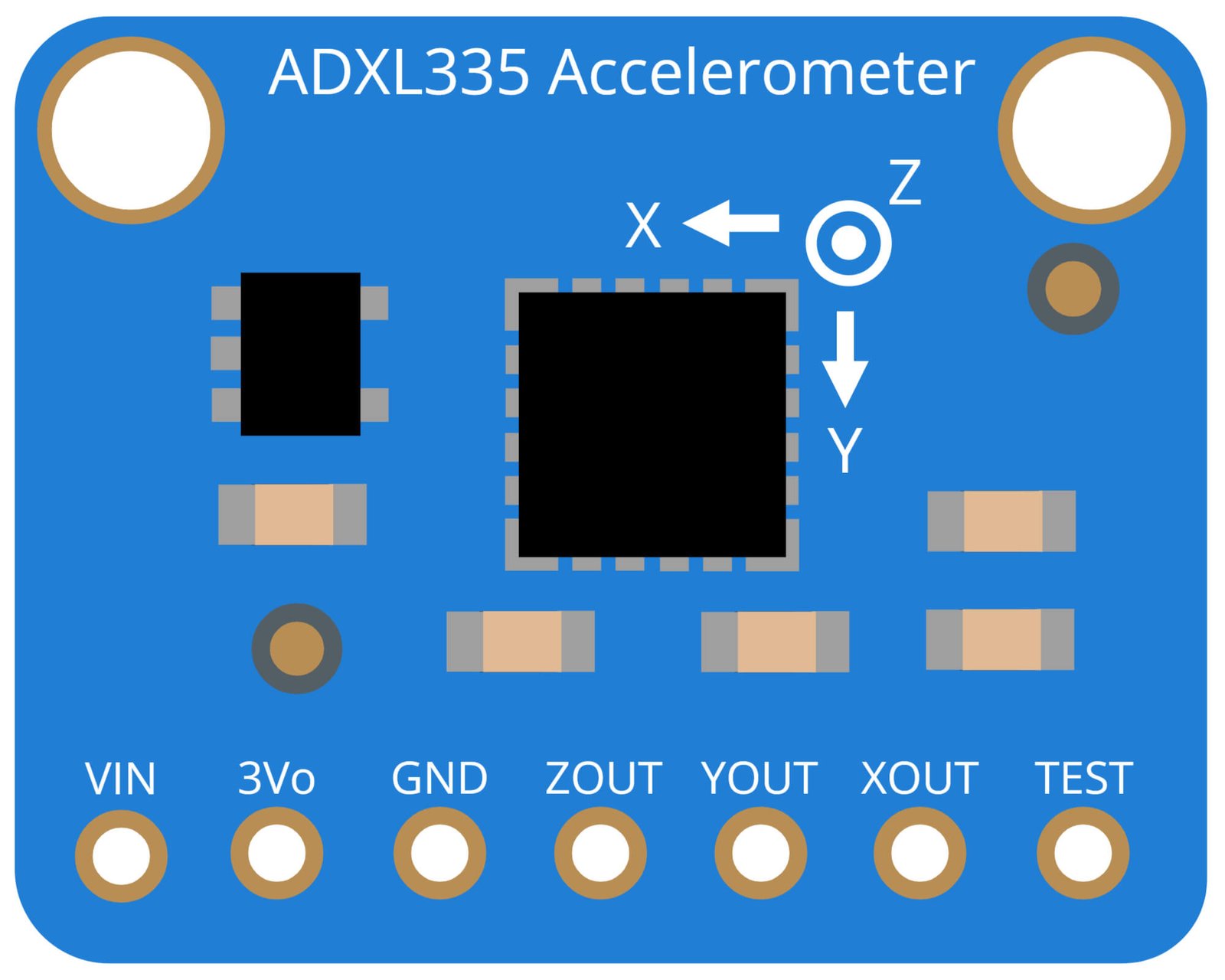
ADXL335 Accelerometer Sensor
The ADXL335 is a low power, three-axis accelerometer sensor. It is capable of measuring acceleration in the range of +/-3g. The sensor measures acceleration along the X, Y, and Z axes and outputs a voltage proportional to the acceleration on each axis. The ADXL335 is widely used in various applications such as motion sensing, gaming, and pedometer devices.
In this project, the ADXL335 sensor is used to detect the movement of the person wearing the device and send data to the Arduino Nano. The Nano then uses an algorithm to calculate the number of steps taken based on the data received from the sensor. The ADXL335’s small size and low power consumption make it a great choice for wearable devices such as pedometers.
The ADXL335 is a highly sensitive sensor that can detect even small movements and vibrations. It has a high resolution of up to 300mV/g, which allows for accurate and precise measurements. The sensor also features a wide operating voltage range of 2.0V to 3.6V, making it compatible with a wide range of microcontroller platforms including the Arduino Nano.
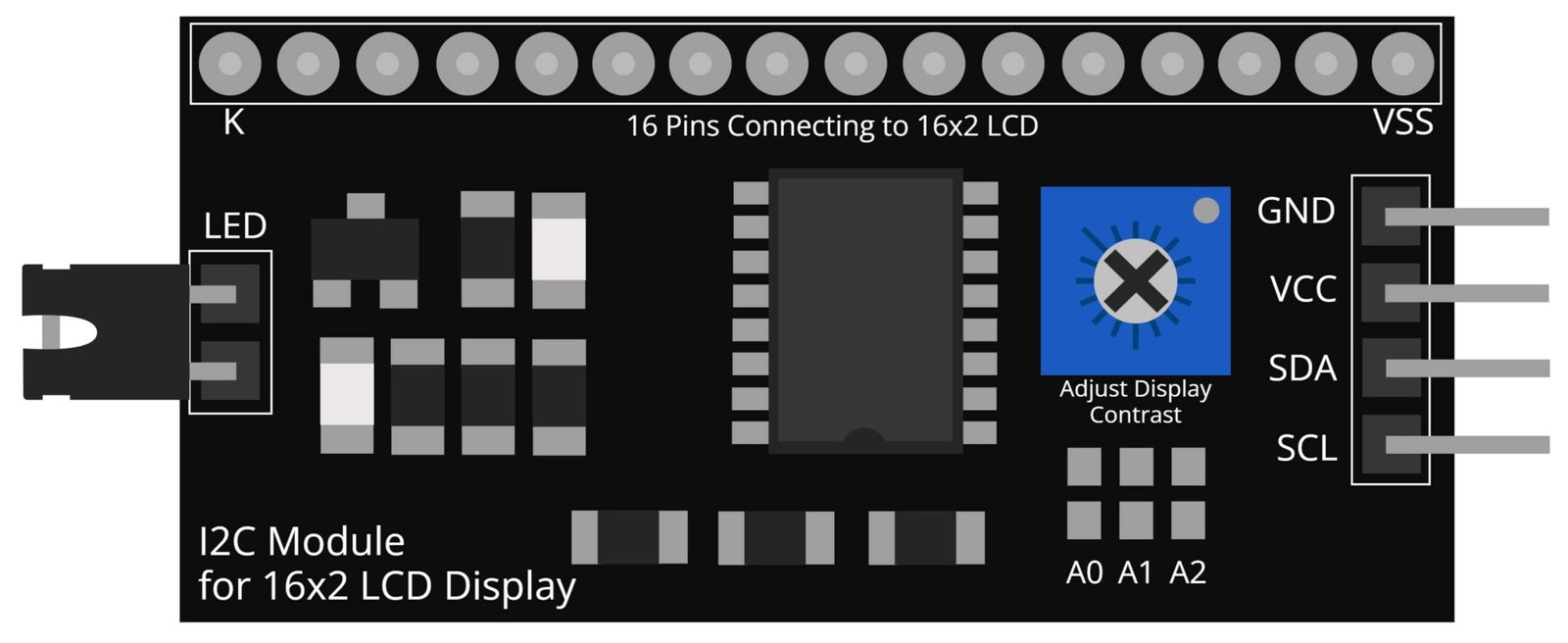
I2C Module for 16×2 LCD Display
The I2C module for 16×2 LCD display is a device that allows for communication between an Arduino Nano microcontroller and a 16×2 LCD display. The I2C interface, also known as TWI (Two-Wire Interface) is a communication protocol that uses only two wires to connect multiple devices together, thus reducing the number of wires needed and making it a cost-effective solution.
In this project, the I2C module for 16×2 LCD display is used to display the number of steps taken on the device. The Arduino Nano sends the data to the I2C module, which then displays the information on the LCD screen. The I2C interface eliminates the need for multiple data and control wires, allowing for a more compact and user-friendly device.
The I2C module for 16×2 LCD display allows for easy control of the display, with simple commands to control the cursor position, text alignment, and display on/off. It also features a built-in contrast control and backlight control, allowing for optimal visibility in any lighting condition.
Steps and info:
1. Get correct components as given. You can buy online or offline. I buy electronics components mostly from Amazon.
2. Start connecting the components. If you are new to connecting components in an electronic circuit, then use a Breadboard or you can straight up make connections using Jumper wires but it will create problem when there will be two or more connections needed at one pin (for example two or more different sensors 5V connection to Arduino’s 5V pin). But before soldering components on a PCB or printing a PCB for your circuit, better try using breadboard so that any errors and mistakes can be observed on breadboard and not after soldering. Or do connections in your way.
3. Now after building the circuit, download the Arduino IDE from https://www.arduino.cc/ website.
4. If you are new to Arduino IDE software, then watch this video we made specially for beginners about Arduino IDE.
5. If you know Arduino IDE then straight up copy the code we given and paste it into the Arduino IDE sketch.
6. Connect the Arduino to your Computer/device. Select a proper port, proper Arduino type and whatever other settings are. Here it is Arduino UNO. (If you don’t know what this all is then watch our video: ).
7. Compile the code and Upload it.
8. If any error occurs then try to troubleshoot it by finding/copy-pasting it into our Solve Errors page https://electronicsprojects.in/solve-errors/, or you can straight up paste the error on Internet and you know the rest. Also check if there are no spelling/syntax errors in the code. Compile the code again once to check if errors are fixed. I have given proper connections and code but still nothing is perfect.
9. Once code compiles and uploads smoothly, you can start testing the working of your circuit/project.
10. Take the circuit and starting tilting it, if there is output(steps) seen on the 16×2 LCD Display then put the circuit in pocket or stick it to your Arm or just keep in hand and start walking/jogging.
11. Keep the ADXL345 Accelerometer in proper position so that it will only tilt when you walk and that tilt will be registered as a step.
12. If it doesn’t work then check connections and code. Also you can talk with me and the community through discord. All the links to social is given at the right side of this page.
Program Code:
/* https://www.electronicsprojects.in Pedometer(Steps Counter) using Arduino, ADXL335 Accelerometer Sensor and 16x2 LCD Display */

#include <LiquidCrystal_I2C.h>
LiquidCrystal_I2C lcd(0x27, 16, 2);
const int xpin = A1;
const int ypin = A2;
const int zpin = A3;
byte p[8] = {
  0x1F,
  0x1F,
  0x1F,
  0x1F,
  0x1F,
  0x1F,
  0x1F,
  0x1F
};
float threshold = 6;
float xval[100] = {0};
float yval[100] = {0};
float zval[100] = {0};
float xavg, yavg, zavg;
int steps, flag = 0;
void setup()
{
  Serial.begin(9600);
  lcd.begin(16,2);
  lcd.backlight();
  lcd.clear();
  calibrate();
}
void loop()
{
  for (int w = 0; w < 16; w++) {
    lcd.write(byte(0));
    delay(500);
  }
  int acc = 0;
  float totvect[100] = {0};
  float totave[100] = {0};
  float xaccl[100] = {0};
  float yaccl[100] = {0};
  float zaccl[100] = {0};
  for (int a = 0; a < 100; a++)
  {
    xaccl[a] = float(analogRead(xpin) - 345);
    delay(1);
    yaccl[a] = float(analogRead(ypin) - 346);
    delay(1);
    zaccl[a] = float(analogRead(zpin) - 416);
    delay(1);
    totvect[a] = sqrt(((xaccl[a] - xavg) * (xaccl[a] - xavg)) + ((yaccl[a] - yavg) * (yaccl[a] - yavg)) + ((zval[a] - zavg) * (zval[a] - zavg)));
    totave[a] = (totvect[a] + totvect[a - 1]) / 2 ;
    Serial.println("totave[a]");
    Serial.println(totave[a]);
    delay(100);
    if (totave[a] > threshold && flag == 0)
    {
      steps = steps + 1;
      flag = 1;
    }
    else if (totave[a] > threshold && flag == 1)
    {
      // Don't Count
    }
    if (totave[a] < threshold   && flag == 1)
    {
      flag = 0;
    }
    if (steps < 0) {
      steps = 0;
    }
    Serial.println('\n');
    Serial.print("Steps: ");
    Serial.println(steps);
    lcd.print("Steps: ");
    lcd.print(steps);
    delay(1000);
    lcd.clear();
  }
  delay(1000);
}
void calibrate()
{
  float sum = 0;
  float sum1 = 0;
  float sum2 = 0;
  for (int i = 0; i < 100; i++) {
    xval[i] = float(analogRead(xpin) - 345);
    sum = xval[i] + sum;
  }
  delay(100);
  xavg = sum / 100.0;
  Serial.println(xavg);
  for (int j = 0; j < 100; j++)
  {
    yval[j] = float(analogRead(ypin) - 346);
    sum1 = yval[j] + sum1;
  }
  yavg = sum1 / 100.0;
  Serial.println(yavg);
  delay(100);
  for (int q = 0; q < 100; q++)
  {
    zval[q] = float(analogRead(zpin) - 416);
    sum2 = zval[q] + sum2;
  }
  zavg = sum2 / 100.0;
  delay(100);
  Serial.println(zavg);
}